Product Description
Balancing Machine for Grinding spindle (PHQ-300)
Modular structure:
Quick change-over from work piece to the next
High balancing accuracy
Infinitely variable DC drive
Optimum operating height
Installation without bolting
Production Description:
Specially designed brackets transmit mechanical force with low vibration damping
Durable and reliable sensor possesses good linearity
Permanent calibration brings high accuracy with a permission of large initial unbalance amount
Belt-driving offers higher precision and easier operation
Advanced electrical measuring system and friendly man-machine interface
Modular design offers a wide range of application
Range of Application:
This balancing machine is widely used in balancing rotatable bodies, such as kinds of medium-sized and small-sized motors rotors, impeller, fans, crankshaft, turbocharger, water pump, roller, grinding wheel, main shaft of machine tool , textile machinery, tool , spindle, etc .. Driven by belt, equipped with Variable speed motor to drive .Which ensures high quality balancing and precision. quick booting ,easy operation. and high efficiency
Special Features:
The measuring unit employs JP-580 Electrical Measuring unit is a system of top function and precision. It can be applied in all kinds of single/double plate and hard/soft bearing machines, and can be connected with different velocity and pressure sensors easily. The unit adopts industrial computer made in Xihu (West Lake) Dis.a Industry Co, which equiped with 17-inch LCD screen and Windows XP Operating System. Featuring with high running speed and reliabilitystrong dustproof and shakeproof ability, it is applicable to various industrial environments
Production Parameters:
| Technical data at a glance | PHQ-160H | PHQ-300H | PHQ-500H |
| Max Mass of Workpiece(kg) | 160 | 300 | 500 |
| Max Diameter of Workpiece (mm) | Φ1000 | Φ1220 | Φ1500 |
| Distance Between Two Support Bearings (mm) | 130~1270 | 130~1270 | 130~1270 |
| Journal Diameter Scope of Workpiece (mm) | Φ 15~753) | Φ 15~753) | Φ 15~753) |
| Diameter Scope of Driving Belt (mm) | Φmax400 | Φmax500 | Φmax600 |
| Rotational Speed when the Diameter of Driving Belt is 100mm (r/min) | 756,11761) | 756,11761) | 756,11761) |
| Motor Power (kw) | 1.52) | 1.52) | 2.22) |
| Length of Bed (mm) | 1500 | 1500 | 1500 |
| Min Achievable Residual Unbalance Amount (emar) | ≤0.5g· mm/kg | ≤0.5g· mm/kg | ≤0.5· mm/kg |
| Type: | Vibration Testing Machine |
|---|---|
| Maxcapacity: | <1000KN |
| Accuracy Grade: | 1 |
| Load Way: | Electronic Load |
| Loading Method: | Dynamic Load |
| Display: | Digital |
| Customization: |
Available
| Customized Request |
|---|
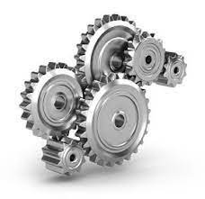
What are some real-world examples of gear pulley systems in action?
Gear pulley systems are utilized in various real-world applications to facilitate mechanical movements, power transmission, and speed control. Here are some examples of gear pulley systems in action:
1. Automobiles:
Gear pulley systems are extensively used in automobiles for various functions. They are employed in the engine's timing belt or timing chain system to synchronize the rotation of the crankshaft and camshaft, ensuring precise valve timing. Gear pulleys are also found in the accessory drive system, where they drive components such as the alternator, power steering pump, water pump, and air conditioning compressor.
2. Industrial Machinery:
In industrial settings, gear pulley systems are found in a wide range of machinery and equipment. They are used in conveyor systems for material handling, where they drive the belts or chains to transport goods or components along the assembly line. Gear pulleys are also utilized in manufacturing machinery, such as printing presses, packaging equipment, and CNC machines, to control movement, power transmission, and speed regulation.
3. Construction Equipment:
Construction equipment, such as cranes, excavators, and concrete mixers, often employ gear pulley systems. Gear pulleys are utilized in the lifting mechanisms of cranes and hoists, enabling controlled lifting and lowering of heavy loads. In excavators, gear pulleys contribute to the movement of the arm, bucket, and tracks. They are also used in concrete mixers to rotate the drum and facilitate the mixing and pouring of concrete.
4. Mining Equipment:
Mining operations rely on gear pulley systems for various applications. Underground mining equipment, such as continuous miners, utilize gear pulleys to drive the cutting heads and conveyor belts. Gear pulleys are also found in surface mining equipment, including draglines and bucket wheel excavators, where they enable the movement and operation of the machinery.
5. Elevators and Escalators:
Gear pulley systems are an integral part of elevators and escalators, facilitating vertical transportation in buildings. They are used in the elevator's traction system to drive the hoist ropes or belts, allowing for smooth and controlled movement of the elevator car. In escalators, gear pulleys drive the steps, ensuring synchronized and safe operation as passengers move between different levels.
6. Agricultural Machinery:
Agricultural machinery often incorporates gear pulley systems for various tasks. Tractors utilize gear pulleys in their power take-off (PTO) system, which transfers power from the engine to agricultural implements such as mowers, balers, or grain augers. Gear pulleys are also used in irrigation systems to drive pumps or control the movement of sprinklers and irrigation lines.
7. Home Appliances:
Gear pulley systems can be found in various home appliances, providing mechanical functions. Washing machines, for example, use gear pulleys in their transmission system to control the agitator or drum movement. Gear pulleys are also employed in exercise equipment, such as stationary bikes or rowing machines, to simulate resistance and enable adjustable workout intensities.
8. Wind Turbines:
Gear pulley systems are utilized in wind turbines to convert the rotational motion of the blades into electricity. They are part of the turbine's gearbox, which increases the rotational speed to match the generator's requirements. Gear pulleys play a crucial role in the power transmission and speed control within the wind turbine system.
In summary, gear pulley systems are widely employed in various real-world applications across different industries. They are utilized in automobiles, industrial machinery, construction equipment, mining machinery, elevators and escalators, agricultural machinery, home appliances, and renewable energy systems like wind turbines. Gear pulleys contribute to mechanical movements, power transmission, and speed control, enabling efficient and reliable operation in these diverse applications.
How are gear pulleys utilized in industrial machinery and conveyor systems?
Gear pulleys play a vital role in industrial machinery and conveyor systems, facilitating the movement of materials and power transmission within these applications. Here's a detailed explanation of how gear pulleys are utilized in industrial machinery and conveyor systems:
Power Transmission:
In industrial machinery, gear pulleys are used for power transmission between different components. They are often employed to transmit rotational motion and torque from an input source, such as an electric motor or an engine, to various output devices or components within the machine. Gear pulleys allow for efficient power transfer and enable the synchronization of different parts of the machinery, ensuring smooth operation and optimal performance.
Speed and Torque Conversion:
Industrial machinery often requires different speeds and torque levels for specific processes or tasks. Gear pulleys are utilized to convert the rotational speed and torque between the input and output shafts. By using gear pulleys with different sizes and ratios, the rotational speed and torque can be adjusted to suit the requirements of the machinery. This allows for precise control over the operation of the equipment and ensures that it operates within the desired speed and torque ranges.
Direction Control:
Conveyor systems in industrial settings often require the ability to control the direction of movement of materials. Gear pulleys are used in these systems to change the direction of rotation and, consequently, the direction of movement. By incorporating gears with different tooth arrangements or by utilizing multiple gear pulleys in specific configurations, conveyor systems can efficiently redirect the flow of materials according to the desired path or process requirements.
Belt and Chain Drives:
Gear pulleys are commonly used in conjunction with belts and chains in industrial machinery and conveyor systems. Belts and chains are wrapped around the pulleys to transfer power and enable the movement of materials. Gear pulleys provide the necessary grip and traction for the belts or chains, ensuring proper power transmission and reliable material handling. The design and arrangement of gear pulleys, belts, and chains can be customized based on the specific application requirements, such as load capacity, speed, and environmental conditions.
Tension Adjustment:
In conveyor systems, maintaining proper tension in the belts or chains is crucial for efficient operation and preventing slippage or excessive wear. Gear pulleys are used to adjust and control the tension in the belts or chains. By incorporating tensioning mechanisms, such as adjustable pulley positions or spring-loaded tensioners, the tension can be regulated to ensure optimal performance and longevity of the conveyor system.
Mechanical Advantage:
Gear pulleys can provide mechanical advantage in industrial machinery and conveyor systems. By utilizing different gear ratios, gear pulleys can amplify or reduce the input torque, enabling the machinery to handle heavier loads or perform tasks that require higher precision. The mechanical advantage provided by gear pulleys enhances the overall efficiency and productivity of industrial processes.
Overall, gear pulleys are essential components in industrial machinery and conveyor systems. They facilitate power transmission, speed and torque conversion, direction control, and tension adjustment. By incorporating gear pulleys into these systems, industries can achieve reliable and efficient operation, improve productivity, and ensure the smooth movement of materials in various manufacturing and industrial applications.
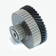
Can you explain the key components and design features of a gear pulley?
A gear pulley system consists of several key components and design features that enable its functionality. Here's an explanation of the key components and design features of a gear pulley:
- Gears: Gears are one of the primary components of a gear pulley system. They are toothed wheels that transmit rotational motion and torque. Gears come in various types, including spur gears, bevel gears, helical gears, and worm gears. The selection of gear type depends on the specific application and requirements of the system. Gears have different sizes, number of teeth, and pitch diameters, which determine the mechanical advantage and speed ratio of the system.
- Pulleys: Pulleys are grooved wheels that use a belt or a rope to transmit motion and force. In a gear pulley system, pulleys are often used in conjunction with gears to provide additional control and flexibility. Pulleys come in different sizes and designs, such as V-belt pulleys and timing belt pulleys. They maintain tension in the belts and ensure efficient power transmission. The grooves on the pulleys guide and grip the belts, preventing slippage and maintaining proper alignment.
- Belts or Ropes: Belts or ropes are flexible elements that connect the pulleys in a gear pulley system. They transmit power and motion from one pulley to another. Belts are commonly made of materials such as rubber or synthetic polymers, while ropes can be made of materials like nylon or steel. The selection of belts or ropes depends on factors like the required strength, flexibility, and operating conditions of the system. Proper tensioning of the belts is crucial to ensure efficient power transmission and prevent slippage.
- Shafts: Shafts are the rotating elements that support the gears and pulleys in a gear pulley system. They provide the axis of rotation for the components and transmit torque from the input to the output. Shafts are usually made of rigid materials such as steel or aluminum. They need to be accurately aligned and supported to ensure smooth and reliable operation of the system. Bearings or bushings are often used to reduce friction and support the shafts.
- Mounting and Housing: The mounting and housing of a gear pulley system refers to the structure that holds and supports the components. The housing provides protection, stability, and alignment for the gears, pulleys, belts, and shafts. It is usually made of metal or plastic and designed to accommodate the specific configuration and size of the gear pulley system. Proper mounting and housing ensure the integrity and durability of the system, preventing excessive vibrations and misalignment.
- Adjustment and Control Mechanisms: Gear pulley systems may incorporate adjustment and control mechanisms to fine-tune the operation and performance. These mechanisms can include adjustable pulley positions, tensioning devices, and speed control mechanisms. By allowing adjustments, the system can adapt to different operating conditions, optimize performance, and accommodate changes in load or speed requirements.
- Safety Features: Depending on the application, gear pulley systems may incorporate safety features such as guards, limit switches, or overload protection mechanisms. These features are designed to ensure the safe operation of the system, prevent accidents, and protect the components from damage. Safety considerations are essential to maintain the integrity and reliability of the gear pulley system.
In summary, a gear pulley system consists of gears, pulleys, belts or ropes, shafts, mounting and housing, adjustment and control mechanisms, and safety features. These components and design features work together to transmit power, control speed and torque, ensure proper alignment and tension, and provide flexibility and adjustability in mechanical systems. By understanding these key components and design features, engineers and designers can create efficient and reliable gear pulley systems for various applications.


editor by CX
2023-10-18