Product Description
Balancing Machine for Grinding spindle (PHQ-300)
Modular structure:
Quick change-over from work piece to the next
High balancing accuracy
Infinitely variable DC drive
Optimum operating height
Installation without bolting
Production Description:
Specially designed brackets transmit mechanical force with low vibration damping
Durable and reliable sensor possesses good linearity
Permanent calibration brings high accuracy with a permission of large initial unbalance amount
Belt-driving offers higher precision and easier operation
Advanced electrical measuring system and friendly man-machine interface
Modular design offers a wide range of application
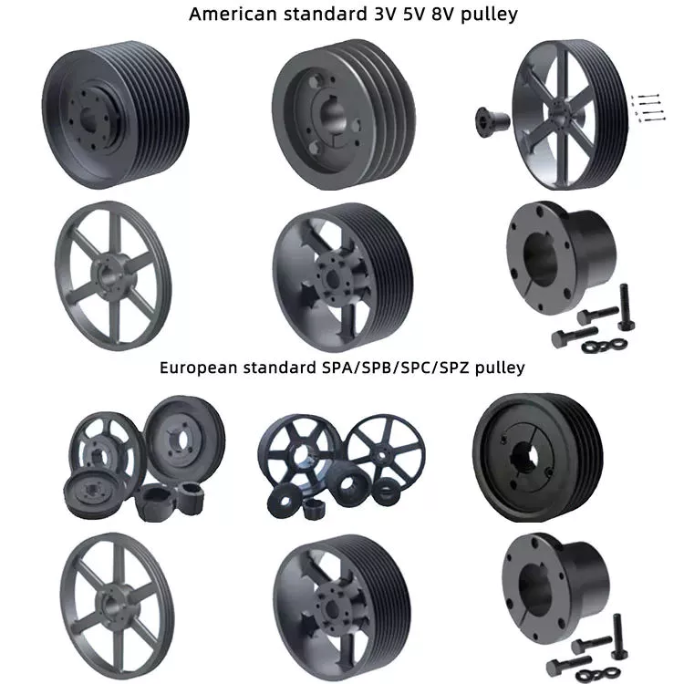
Range of Application:
This balancing machine is widely used in balancing rotatable bodies, such as kinds of medium-sized and small-sized motors rotors, impeller, fans, crankshaft, turbocharger, water pump, roller, grinding wheel, main shaft of machine tool , textile machinery, tool , spindle, etc .. Driven by belt, equipped with Variable speed motor to drive .Which ensures high quality balancing and precision. quick booting ,easy operation. and high efficiency
Special Features:
The measuring unit employs JP-580 Electrical Measuring unit is a system of top function and precision. It can be applied in all kinds of single/double plate and hard/soft bearing machines, and can be connected with different velocity and pressure sensors easily. The unit adopts industrial computer made in Xihu (West Lake) Dis.a Industry Co, which equiped with 17-inch LCD screen and Windows XP Operating System. Featuring with high running speed and reliabilitystrong dustproof and shakeproof ability, it is applicable to various industrial environments
Production Parameters:
| Technical data at a glance | PHQ-160H | PHQ-300H | PHQ-500H |
| Max Mass of Workpiece(kg) | 160 | 300 | 500 |
| Max Diameter of Workpiece (mm) | Φ1000 | Φ1220 | Φ1500 |
| Distance Between Two Support Bearings (mm) | 130~1270 | 130~1270 | 130~1270 |
| Journal Diameter Scope of Workpiece (mm) | Φ 15~753) | Φ 15~753) | Φ 15~753) |
| Diameter Scope of Driving Belt (mm) | Φmax400 | Φmax500 | Φmax600 |
| Rotational Speed when the Diameter of Driving Belt is 100mm (r/min) | 756,11761) | 756,11761) | 756,11761) |
| Motor Power (kw) | 1.52) | 1.52) | 2.22) |
| Length of Bed (mm) | 1500 | 1500 | 1500 |
| Min Achievable Residual Unbalance Amount (emar) | ≤0.5g· mm/kg | ≤0.5g· mm/kg | ≤0.5· mm/kg |
/* January 22, 2571 19:08:37 */!function(){function s(e,r){var a,o={};try{e&&e.split(",").forEach(function(e,t){e&&(a=e.match(/(.*?):(.*)$/))&&1
| Type: | Vibration Testing Machine |
|---|---|
| Maxcapacity: | <1000KN |
| Accuracy Grade: | 1 |
| Load Way: | Electronic Load |
| Loading Method: | Dynamic Load |
| Display: | Digital |
| Customization: |
Available
| Customized Request |
|---|
How do gear pulleys contribute to the functioning of garage door systems?
In garage door systems, gear pulleys play a vital role in ensuring the smooth and efficient operation of the doors. They are instrumental in facilitating the movement, power transmission, and safety features of the garage door systems. Here's a detailed explanation of how gear pulleys contribute to the functioning of garage door systems:
1. Lifting Mechanism:
Garage doors typically utilize a lifting mechanism to raise and lower the door. Gear pulleys are a crucial component of this mechanism. They are connected to the motor or drive unit and work in conjunction with cables, chains, or belts to transfer the rotational motion from the motor to the door. The gear pulleys convert the rotary motion into a linear motion, allowing the door to be lifted or lowered smoothly and effortlessly.
2. Mechanical Advantage:
One of the key functions of gear pulleys in garage door systems is to provide a mechanical advantage. By utilizing different pulley sizes and ratios, gear pulleys enable the motor to exert the necessary force to lift heavy garage doors. The mechanical advantage achieved through the gear pulleys allows for efficient operation, reducing the strain on the motor and other components of the system.
3. Speed Control:
Gear pulleys also contribute to speed control in garage door systems. By using different pulley sizes and ratios, the speed at which the door opens or closes can be adjusted. This allows homeowners to customize the speed of the garage door operation according to their preferences and specific requirements. Gear pulleys enable precise speed control, ensuring smooth and controlled movement of the door.
4. Counterbalance System:
Garage doors often utilize a counterbalance system to offset the weight of the door and make it easier to lift. Gear pulleys are an integral part of this system. They are connected to the torsion springs or extension springs, which store and release energy to assist in lifting and lowering the door. The gear pulleys transmit the force exerted by the springs to the door, allowing for efficient counterbalancing and smoother operation.
5. Safety Features:
Gear pulleys contribute to the safety features of garage door systems. Many modern garage doors are equipped with safety sensors and mechanisms to prevent accidents or damage. Gear pulleys are often connected to these safety features, such as the photoelectric sensors or the emergency release mechanism. The gear pulleys ensure that these safety features operate in sync with the door movement, providing reliable and effective protection.
6. Maintenance and Lubrication:
Regular maintenance and lubrication of gear pulleys are essential for the proper functioning of garage door systems. Lubricating the gear pulleys helps reduce friction and wear, ensuring smooth operation and prolonging the lifespan of the components. Regular inspection of the gear pulleys allows for early detection of any misalignment, damage, or wear, enabling timely repairs or replacements to maintain the optimal functioning of the garage door system.
In conclusion, gear pulleys are essential components that contribute significantly to the functioning of garage door systems. They play a vital role in the lifting mechanism, providing a mechanical advantage, facilitating speed control, enabling the counterbalance system, incorporating safety features, and requiring regular maintenance and lubrication. Properly functioning gear pulleys ensure the smooth and efficient operation of garage doors, providing convenience, security, and peace of mind to homeowners.
How are gear pulleys integrated into HVAC systems and air conditioning units?
In HVAC systems and air conditioning units, gear pulleys play a crucial role in transmitting mechanical power and facilitating the operation of various components. Here's a detailed explanation of how gear pulleys are integrated into HVAC systems and air conditioning units:
1. Belt-Driven Systems:
Many HVAC systems and air conditioning units use belt-driven systems, where gear pulleys are employed to transfer power from the motor to other components. A motor-driven belt rotates the gear pulley, which, in turn, rotates the driven pulley. The driven pulley is connected to other components such as fans, blowers, or compressors. This arrangement allows the motor to drive multiple components simultaneously.
2. Variable Speed Applications:
Some HVAC systems and air conditioning units require variable speed control to optimize energy efficiency and provide precise temperature control. Gear pulleys, along with variable speed drives, are used in such applications. The gear pulleys help adjust the rotational speed of components, such as fans or compressors, by changing the pulley diameter ratio. This allows for fine-tuning of the system's performance based on the desired conditions.
3. Fan and Blower Assemblies:
Gear pulleys are commonly used in fan and blower assemblies within HVAC systems and air conditioning units. The motor drives the gear pulley, which is connected to the fan or blower shaft through a belt. As the gear pulley rotates, it transfers power to the fan or blower, causing them to spin and circulate air. The gear pulleys help achieve the desired airflow rates and provide the necessary mechanical power for efficient operation.
4. Compressor Systems:
In air conditioning units, gear pulleys are often used in compressor systems. The compressor plays a vital role in the refrigeration cycle by compressing the refrigerant gas, raising its pressure and temperature. Gear pulleys are used to transmit power from the motor to the compressor, allowing it to perform its compression function. Proper selection and sizing of gear pulleys are crucial to ensure optimal compressor performance and system efficiency.
5. Tensioning and Alignment:
Proper tensioning and alignment of the belt and gear pulley system are essential for efficient and reliable operation. Tensioning devices, such as idler pulleys or tensioners, are often incorporated into HVAC systems and air conditioning units to maintain the appropriate tension in the belt. This helps prevent slippage, minimize power losses, and ensure the gear pulleys effectively transmit power to the driven components.
6. Maintenance and Replacement:
Regular maintenance and inspection of gear pulleys are necessary to ensure their continued performance and prevent unexpected failures. This may involve checking for wear, misalignment, or damage to the gear teeth or pulley surfaces. If any issues are detected, timely replacement of the gear pulleys is essential to avoid disruptions in the HVAC system or air conditioning unit's operation.
In summary, gear pulleys are integrated into HVAC systems and air conditioning units through belt-driven systems, variable speed applications, fan and blower assemblies, compressor systems, and proper tensioning and alignment mechanisms. These gear pulley arrangements enable the transfer of mechanical power, control of rotational speed, and efficient operation of various components within the HVAC system or air conditioning unit. Regular maintenance and inspection are necessary to ensure the gear pulleys' reliability and performance.
How does the gear mechanism work within a gear pulley system?
In a gear pulley system, the gear mechanism plays a crucial role in transmitting mechanical power between rotating shafts. Here's a detailed explanation of how the gear mechanism works within a gear pulley system:
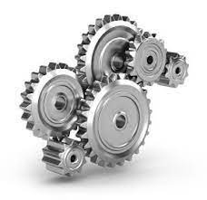
The gear mechanism consists of two or more gears with interlocking teeth that mesh together. Each gear has a specific number of teeth and is mounted on a shaft. When the gears are connected within the system, they engage with each other and transfer rotational motion and torque from the driving gear to the driven gear.
Here's how the gear mechanism works within a gear pulley system:
- Meshing of Gears: The gear mechanism starts with the meshing of gears. The teeth of one gear interlock with the teeth of another gear, creating a mechanical connection between them. The gears are positioned in such a way that their teeth engage properly, ensuring smooth and efficient power transmission.
- Rotation of the Driving Gear: The gear pulley system has a driving gear that receives rotational motion and torque from the power source, such as an electric motor or an engine. As the driving gear rotates, it transfers its rotational motion to the meshed gears.
- Transfer of Rotational Motion: When the driving gear rotates, the interlocking teeth of the meshed gears transmit the rotational motion to the driven gear. The rotation of the driving gear causes the driven gear to rotate in the opposite direction or in the same direction, depending on the arrangement of the gears.
- Speed and Torque Conversion: The gear mechanism enables speed and torque conversion within the gear pulley system. The ratio of the number of teeth on the driving gear to the number of teeth on the driven gear determines the speed and torque relationship between them. When the driving gear has a larger number of teeth than the driven gear, it results in speed reduction and torque amplification. Conversely, when the driven gear has more teeth, it leads to speed amplification and torque reduction.
- Direction Control: The arrangement of gears within the gear pulley system determines the direction of rotation. By meshing gears in specific configurations, the direction of rotation can be changed as needed. For example, meshing two gears with the same number of teeth results in the same direction of rotation, while meshing gears with a different number of teeth causes the driven gear to rotate in the opposite direction.
- Multiple Gear Systems: Gear pulley systems often incorporate multiple gears to achieve specific speed, torque, and direction requirements. By adding intermediate gears, idler gears, or compound gear arrangements, complex gear systems can be created to transmit power efficiently and adapt to the needs of the driven components. Multiple gears allow for more precise control over speed and torque, as well as the distribution of power to multiple output shafts.
The gear mechanism within a gear pulley system enables the efficient transmission of mechanical power, speed and torque conversion, direction control, and the creation of versatile power transmission systems. By utilizing the interlocking teeth of gears, gear pulley systems can effectively transfer rotational motion and torque between rotating shafts, enabling various applications in industries such as automotive, manufacturing, and machinery.


editor by CX
2024-04-30